



Posted in الانترنت والشبكات, معدات الشبكات on نوفمبر 09, 2026
PoE Power Budget Planning for Business Networks

Future Networks | Enterprise Networking
An office may have enough Ethernet ports for every planned access point and camera, yet lack sufficient electrical capacity to operate them together. Port count and available Power over Ethernet capacity are related but separate specifications.
PoE design requires checking the power delivery standard, per-port capability, total switch budget, cable conditions, device operating modes, and expansion requirements.
This article from Future Networks provides a structured method for evaluating those requirements before installing or expanding a business network.
 Call Now
 WhatsApp
Quick Answer
List each powered device and its documented PSE power requirement. Confirm the appropriate IEEE PoE standard and the switch's per-port power class. Sum the relevant planned allocations, compare the total with the switch power budget, and allow justified room for future devices. Validate the complete design using compliant cabling and real commissioning tests.

1. Understand the Power Delivery Architecture
Power over Ethernet uses power sourcing equipment, or PSE, to supply compatible powered devices, or PDs, through suitable Ethernet cabling. Managed switches and compatible injectors can act as power sources.
Not every network port supplies electricity. Likewise, a passive-power device should not be assumed compatible with standards-based PoE equipment simply because the connector fits.
2. Understand the Standard Power Classes
IEEE 802.3af, 802.3at, and 802.3bt define different power delivery capabilities. The power allocated at the source is not necessarily the same as the maximum power available at the powered device.
Before procurement, check the actual source standard, the powered device requirement, and any manufacturer-specific operating constraints.
| Standard | Maximum PSE Power | Maximum PD Power | Design Note |
|---|---|---|---|
| 802.3af | 15.4 W | 12.95 W | Check device compatibility |
| 802.3at | 30 W | 25.5 W | Commonly called PoE+ |
| 802.3bt Type 3 | 60 W | 51 W | Higher-power allocation |
| 802.3bt Type 4 | 90 W | 71.3 W | Review cabling and thermal conditions |
3. Per-Port Capacity Is Not Total Switch Capacity
A switch may advertise a particular maximum power class for individual ports but have an aggregate power budget that prevents every port from reaching that maximum simultaneously.
Review the vendor's total PoE budget, power-supply options, port groups, and any restrictions on simultaneous allocations. The switch's own electricity consumption is not necessarily included in the published PoE output budget.
4. Build a Device Power Register
Record device model, interface standard, maximum required power, quantity, operational features, and planned port assignment. Camera heaters, additional radios, and other functions can change requirements depending on the product.
Use official technical specifications rather than category averages when establishing a procurement requirement.
5. Calculate the Required Capacity
Multiply the planned source-side allocation for each device type by its quantity, then sum those amounts. Compare the total with the switch budget and review a justified expansion allowance.
Consider the switch's power management behavior: some allocate based on the declared class, while others have additional capabilities. The design should match the actual equipment configuration.
| Hypothetical Device | Quantity | Source Allocation | Subtotal |
|---|---|---|---|
| Access point group | 5 | 30 W | 150 W |
| IP device group | 4 | 15.4 W | 61.6 W |
| Other powered devices | 3 | 15.4 W | 46.2 W |
| Illustrative total | 12 | — | 257.8 W |
This is an arithmetic illustration, not the specification of any supplied product or completed installation. Actual requirements must be checked against the chosen models.
6. Account for Cable Loss and Installation Conditions
Power transmission is affected by conductor resistance, channel length, connection quality, and temperature. High-power installations also require attention to bundled cable conditions and applicable cabling guidance.
Do not treat an Ethernet link that passes data traffic as proof that the power path meets every required condition.
7. Evaluate Higher-Power Equipment Separately
Some advanced devices need higher power classes or support limited functionality when supplied below their preferred requirement. Check whether essential features remain available at the planned power level.
Different power input methods, proprietary injectors, and optional accessories must be evaluated individually rather than assumed interchangeable.
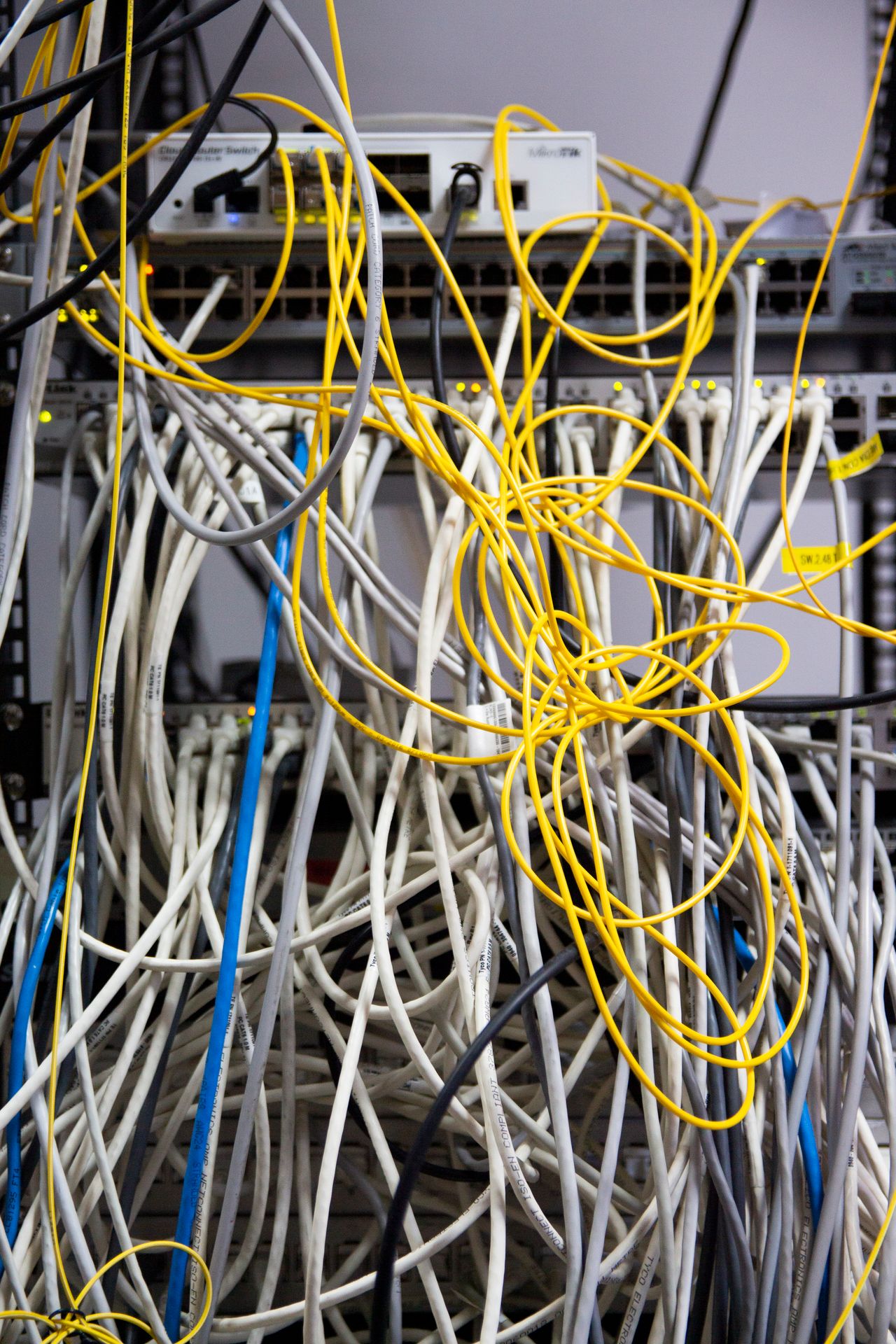
8. Plan Port Allocation and Device Priorities
When a switch approaches its power limit, certain platforms can prioritize devices or manage allocated power. This behavior varies by model and configuration.
Determine the consequences of losing each powered device and decide whether the chosen equipment can meet the business requirement without relying on undocumented fallback behavior.
9. Troubleshoot Power Symptoms Systematically
Unexpected device restarts, failed power negotiation, power-budget warnings, and reduced device functionality may indicate a supply issue, but they can also result from cables, firmware, or hardware faults.
Use switch status, event logs, device specifications, and suitable test procedures to isolate the cause. Avoid increasing power or changing wiring without confirming compatibility.
| Symptom | Potential Cause | Evidence | Next Step |
|---|---|---|---|
| Device does not start | Incompatible or insufficient power | Port and device specifications | Verify supported source |
| Intermittent restart | Power, cable, or device fault | Events and physical tests | Isolate contributing cause |
| Additional ports denied | Exhausted budget | Allocated power total | Redesign capacity |
| Feature unavailable | Reduced-power operation | Vendor operating status | Provide compliant power |
10. Commissioning and Acceptance Tests
Test representative device operating conditions, confirm that every planned device receives supported power, and inspect the switch's remaining budget. Validate the installed cabling against the project requirements.
Record the tested models, port locations, software state, power status, and any outstanding limitations. A successful boot alone is not sufficient evidence for all use cases.
11. Hypothetical Expansion Scenario
A Saudi office plans to add wireless access points to an existing PoE switch. The switch has free physical ports, but its current power budget is nearly allocated.
The team reviews device documentation and actual switch capability before connecting the new units. It may need another compliant power source or a different switch design. This scenario is illustrative rather than a claim about a completed installation.
12. Common Mistakes and Design Checklist
- Confusing port count with available power.
- Using device averages instead of documented requirements.
- Ignoring source-versus-device power differences.
- Assuming all ports deliver maximum power together.
- Overlooking cable quality and length.
- Mixing passive and standards-based power incorrectly.
- Ignoring high-power device features.
- Planning no expansion capacity.
- Failing to review supply restrictions.
- Accepting a system without real testing.
☐ Device inventory complete. ☐ Standards verified. ☐ Per-port limits reviewed. ☐ Total budget calculated. ☐ Cabling suitable. ☐ Features supported. ☐ Capacity allowance justified. ☐ Ports assigned. ☐ Commissioning recorded. ☐ Future changes documented.
| Acceptance Area | Required Proof | Pass Criterion | Failure Response |
|---|---|---|---|
| Compatibility | Vendor specifications | Supported standards | Correct source selection |
| Capacity | Power calculation | Adequate budget | Redesign allocation |
| Operation | Device functionality test | Required features available | Investigate |
| Documentation | Device and port register | Traceable allocation | Complete records |

13. FAQs and Conclusion
Does a 24-port PoE switch support 24 maximum-power devices?
Only if the per-port and aggregate budgets allow the required simultaneous allocations.
Can a powered device negotiate less power?
Behavior depends on the applicable standard and device capabilities. Essential features should be verified under the intended supply condition.
Do cables influence PoE performance?
Yes. Resistance, connection quality, length, and installation conditions are relevant.
Is Passive PoE interchangeable with IEEE PoE?
No. Specific voltage and wiring requirements must be verified before connecting equipment.
When is a different switch required?
When the current equipment cannot satisfy the necessary power, compatibility, port, and operating requirements.
A reliable PoE design balances electrical capacity, networking requirements, and realistic future expansion. The correct purchasing decision follows verified device specifications and testing, not the headline number of Ethernet ports.
Visit the official Future Networks website for business networking information.
This post is part of a series called Post